Commercial EV Applications
- Electric Bus
- Truck
- Off-road Vehicle
- Prototype Vehicle
- Specialty Vehicle
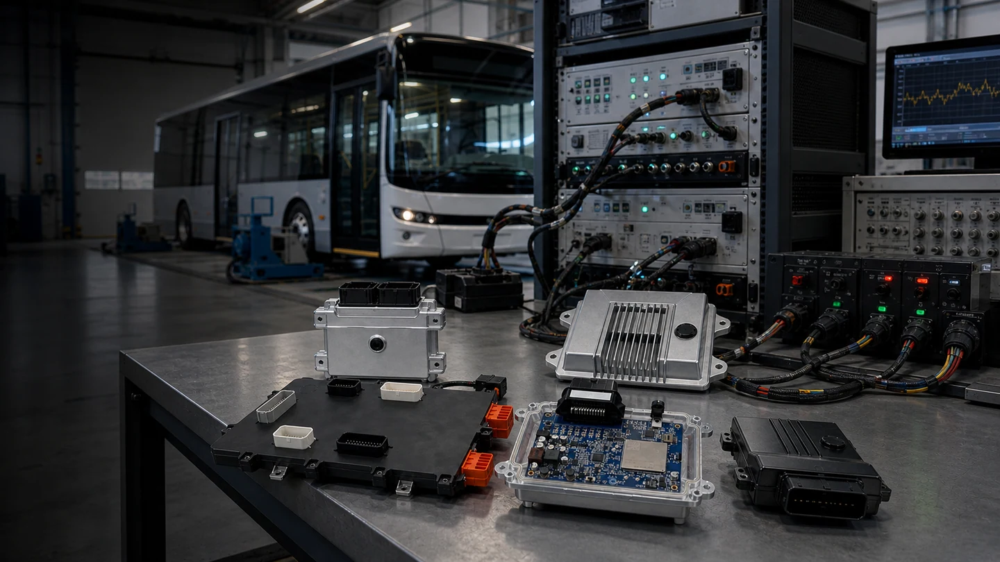
KCU GEN1 is a highly configurable Vehicle Control Unit (VCU) platform for commercial EV applications, electric buses, trucks, prototype vehicles, and specialty vehicle integration.
Discuss KCU GEN1 VCU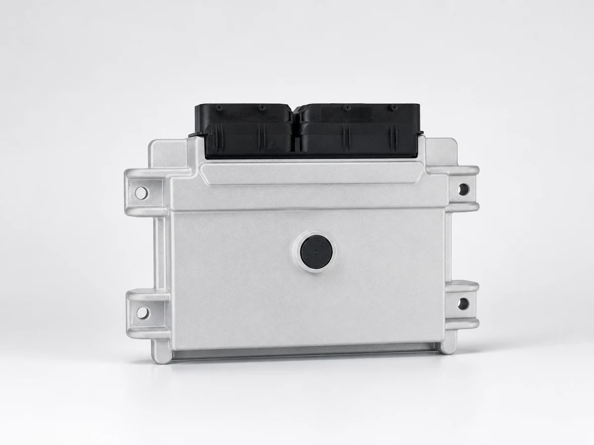
Vehicle Control Unit Product Landing Page
KCU GEN1 is a Commercial EV Vehicle Control Unit (VCU) that acts as the vehicle-control core for powertrain coordination, BMS integration, EVCC integration, body control, vehicle networking, diagnostics, and calibration. This product page positions KCU GEN1 as a Vehicle Control Unit, not as a generic controller.
Engineering Details
KCU GEN1 remains a concrete product page for engineering evaluation, sourcing, and vehicle integration. The following sections keep the control core, I/O, communication, power, mechanical, and automotive-design information visible for users.
15 analog inputs, 44 digital inputs, 4 frequency inputs, plus high-side and low-side power outputs.
4 CAN 2.0B channels and 1 LIN Master for BMS, motor controller, body controller, and diagnostic-equipment integration.
High-side and low-side outputs support overcurrent, overtemperature, short-circuit, and open-load diagnostics.
CAN termination, passive components, I/O mapping, and control logic can be adjusted by project need.
Technical Specifications
Applications
Acts as a VCU core integrating powertrain, body, energy, and vehicle-network data.
CAN and I/O interfaces connect battery status, protection logic, and vehicle control strategy.
Build prototype control, I/O validation, HIL testing, and vehicle bench workflows quickly.
Suitable for commercial vehicles, construction equipment, agricultural machinery, and low-speed mobility.
These links connect the VCU product page with AUTOSAR, EVCC, BCM, automotive AI, diagnostics, cybersecurity, and commercial EV controller topic clusters.