Body Domain Controller

KCU BCM

A body domain controller for electric buses and commercial vehicles, integrating front/rear BCM, lighting, doors, HVAC, wipers, ADAS/IVI power, and high-density 24V load control.

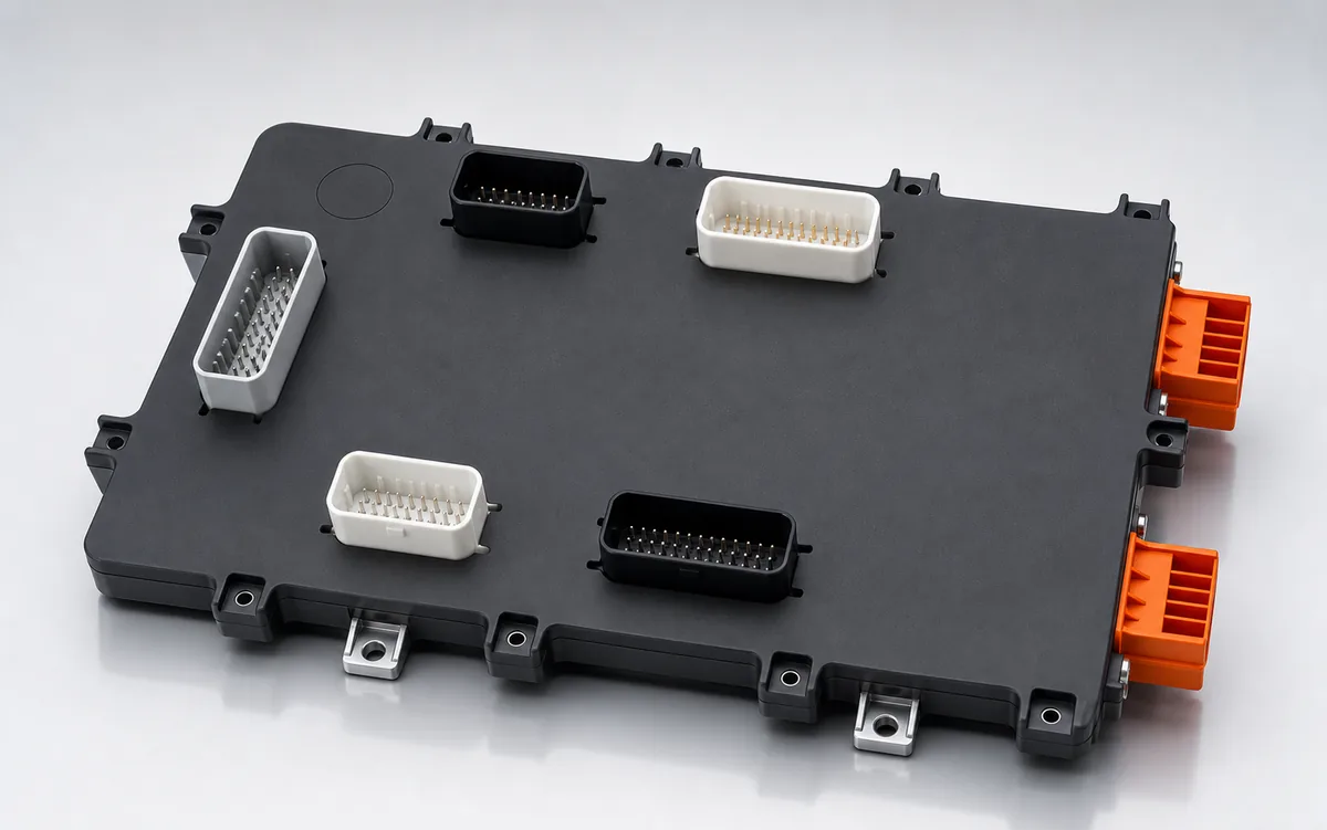
KCU BCM product studio photo

Positioning

A body domain controller for electric buses and commercial vehicles, integrating front/rear BCM, lighting, doors, HVAC, wipers, ADAS/IVI power, and high-density 24V load control.

Each KCU-BCM integrates 56 signal inputs, 50 power/actuator outputs, four sensor-supply channels, and multiple in-vehicle networks.

Front and rear BCMs use identical hardware: the front unit aggregates strategy and diagnostics, while the rear unit executes rear-body I/O over CAN FD.

Designed for 9–32 V commercial-vehicle electrical systems, with up to 200 A and 2,000 W per module plus per-channel electrical diagnostics and protection.

System Architecture

Think of KCU-BCM as the sensing, decision, and protected power-distribution center for body electronics. It reads switches, sensors, and network commands, evaluates vehicle state, then safely drives doors, lighting, wipers, fans, and other 24 V loads.

BODY SIGNAL AND LOAD CONTROL 9–32 V · CAN FD · LIN · Ethernet*
01 | VEHICLE INPUTS

Power, signals, and networks

Receives body switches, sensors, and commands from other ECUs while managing the 9–32 V supply and wake-up sources.

56 inputs: SG 28, SP 16, frequency 4, analog 4, resistive 4
CAN FD ×3, LIN ×1, 100BASE-T1 ×1 (optional)
02 | CONTROL CORE

KCU BCM

The S32K344 executes body strategies, interlocks, diagnostics, and security, then decides when each load may operate.

State machines, safety interlocks, and power sequencing
UDS diagnostics, degraded modes, and Inter-BCM coordination
03 | PROTECTED OUTPUTS

Power drivers and body loads

Current-monitored, fault-protected driver stages operate the front and rear body equipment.

50 outputs: HSD 36, half-bridge 6, LSD 8
Doors, lighting, wipers, HVAC, pumps, and ADAS / IVI power

How do the front and rear BCMs share the work?

Both units use identical hardware and are placed near their local wiring. Strategy stays in the front BCM; the rear BCM executes nearby outputs and returns diagnostics.

Front BCM (functional master)

Runs body strategy, state machines, safety evaluation, diagnostic aggregation, and the UDS gateway, while controlling front lighting, front doors, wipers, horn, EPS, and front ADAS power.

Inter-BCM CAN FD · signal synchronization ≤ 100 ms

Rear BCM (I/O executor)

Controls rear lighting, rear doors, cooling fans, pumps, rear cameras, and cabin electronics, and reports local open-load, short-circuit, over-current, and over-temperature faults.

Important: Master/Slave describes functional responsibility, not redundancy. Roles do not fail over automatically; the rear BCM enters its defined safe state if the master is lost.

Specifications

Signal Inputs | 56 channels
Switch-to-ground (SG) 28 channels | active-low, wake-up capable
Programmable switch (SP) 16 channels | configurable active high/low, wake-up capable
Frequency input 4 channels | wheel-speed, rotation-speed, or pulse signals
Analog input 4 channels | 0–5 V DC
Resistive input 4 channels | 2 × 100 Ω–200 kΩ; 2 × 100 Ω–2 kΩ
High-side Power Outputs | 36 channels
HSD 30 A 1 channel | highest-priority load such as EPS
HSD 20 A 3 channels | fans, pumps, and blowers
HSD 15 A 10 channels | headlamps, wipers, horns, and heaters
HSD 5 A 6 channels | turn, brake, reverse lamps, and DRL
HSD 3 A 8 channels | marker/door lamps and ADAS/camera/IVI
HSD 1 A 8 channels | LEDs, displays, and low-power modules
Other Outputs & Sensor Supplies
Half-bridge 4.5 A 6 channels | bidirectional actuation; thermal simulation in progress
Low-side driver 3 A 8 channels | buzzers, relays, and low-power actuators
5 V sensor supply 2 channels | 50 mA each with short/over-current protection
12 V sensor supply 2 channels | 100 mA each with short/over-current protection
Output protection Open-load, short-to-ground/battery, over-current, and over-temperature detection
In-vehicle Networks
CAN FD 3 channels | one wake-up channel; VCU, T-BOX, ADAS, and Inter-BCM
LIN Master 1 channel | wake-up capable for HVAC and local subnetworks
100BASE-T1 1 optional channel | high-speed diagnostics and OTA
Address setting 4-bit | identifies front/rear BCM nodes
Inter-BCM Dedicated CAN FD protocol; signal synchronization requirement ≤ 100 ms
Processing Core & Safety
MCU NXP S32K344 | Arm Cortex-M7 Lockstep, up to 160 MHz
Memory 4 MB Flash / 512 KB RAM
Hardware security HSE, Secure Boot, and protected key storage
Functional-safety mechanisms Lockstep, RAM/Flash ECC, window watchdog, voltage/clock monitoring
Firmware update AB Swap dual-partition update with rollback
Power & Environmental Capability
Operating voltage 9–32 V DC
Output capability Up to 200 A and 2,000 W per module
Input protection Reverse-polarity and automotive transient protection
Low-power mode Sleep/LPOFF with CAN, LIN, ACC/IGN, and external-input wake-up
Environment -40 °C to +85 °C; target IP67 / ISO 16750

Specifications reflect the EVT-stage product specification. Ethernet is optional, half-bridge 4.5 A thermal simulation remains in progress, and final connectors, dimensions, and weight are subject to the released technical document.

Software Functions

A body domain controller for electric buses and commercial vehicles, integrating front/rear BCM, lighting, doors, HVAC, wipers, ADAS/IVI power, and high-density 24V load control.

Body Domain State Machine
Door Safety Logic with speed interlock and anti-pinch evaluation
Cooling / fan derating algorithm
Diagnostic Manager and fault aggregation
Lighting strategy engine
Wiper / washer logic with VCU-driven modes
ADAS / IVI power management with delay-off logic
Security Manager with MAC, freshness counter and authentication
Inter-BCM protocol handler

Need BCM architecture planning or custom I/O?

We can help plan BCM integration around vehicle platform topology, front/rear body layout, 24V loads, diagnostics, and Inter-BCM communication.

Contact us