
Vehicle-level virtual plant
Combine body, chassis, powertrain, braking, steering, tires, and Driver / Pilot interfaces into an executable model.
Whole-Vehicle Virtual Plant and Simulation Tool
Bring vehicle models, control sources, environment, simulation execution, and result analysis into one vehicle-level virtual plant workspace.
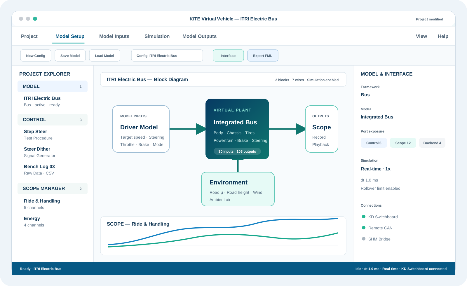
A vehicle-simulation workflow from model definition to execution results
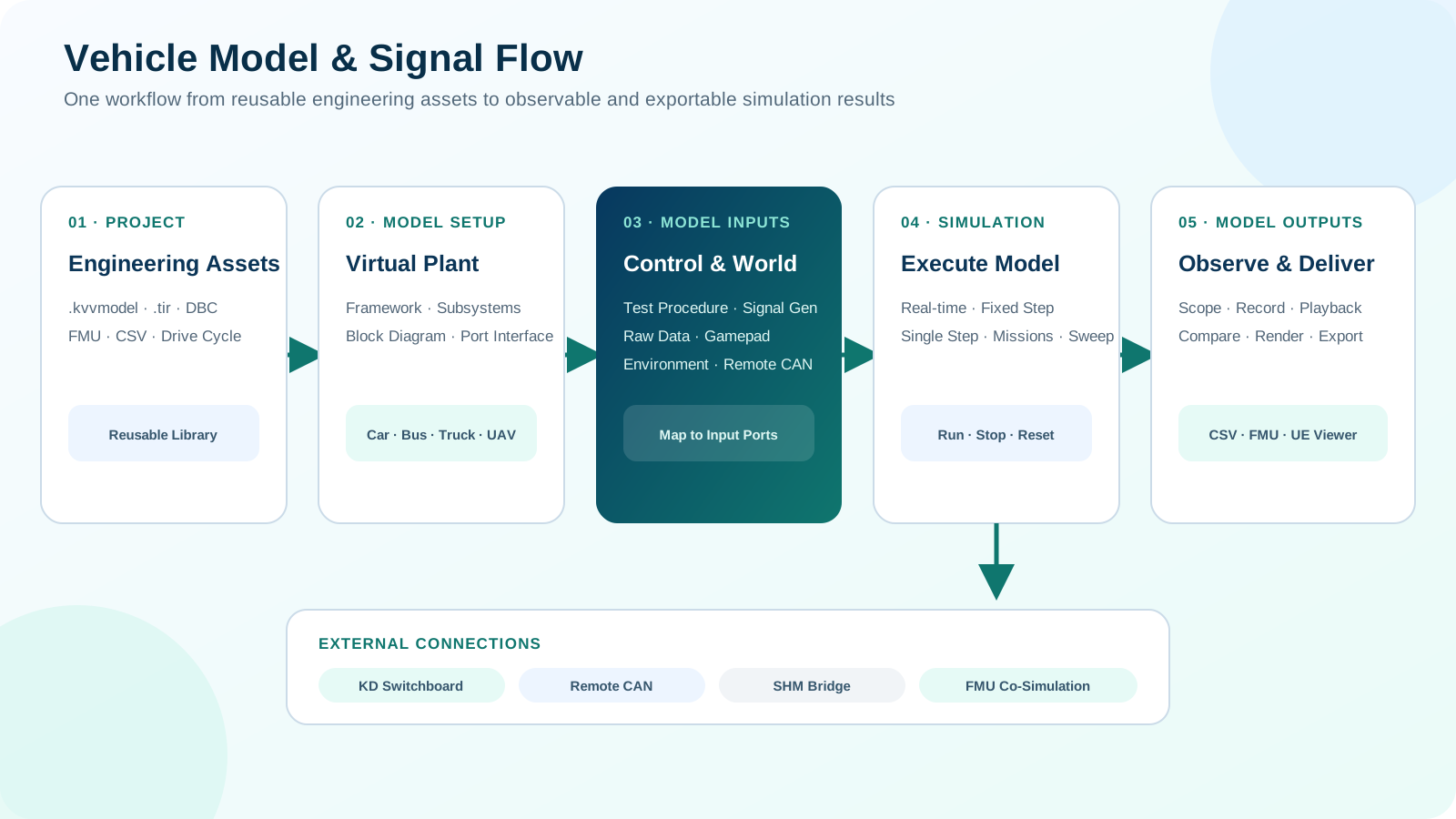
KITE Virtual Vehicle organizes whole-vehicle simulation around Project, Model Setup, Model Inputs, Simulation, and Model Outputs. Engineers start from car, bus, truck, two-wheeler, or aerial vehicle frameworks; configure body, chassis, powertrain, braking, steering, tires, and port interfaces; then connect control procedures, raw data, gamepads, Remote CAN, SHM, and environment conditions. Results can be reviewed through scopes, recordings, playback, missions, and parameter sweeps, then connected downstream through FMU, CSV, KD Switchboard, or UE Viewer.
Combine body, chassis, powertrain, braking, steering, tires, and Driver / Pilot interfaces into an executable model.
Manage the model lifecycle and signal direction through Model Setup, Model Inputs, Simulation, and Model Outputs.
Use real-time, fixed-step, single-step, missions, and parameter sweeps for different validation tasks.
Use simulation results through scopes, playback, CSV, FMU, KD Switchboard, and UE Viewer.
KITE Virtual Vehicle brings frameworks, vehicle configuration, block diagrams, port interfaces, control sources, environment conditions, simulation execution, and scope-based result analysis into one vehicle-level workspace for model creation, input mapping, and result inspection.
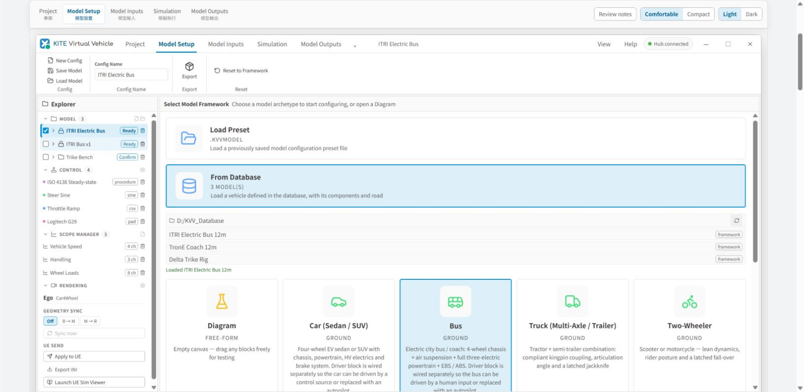
Screen 01 / 10
Start from a .kvvmodel preset, the model database, or a diagram, then select the vehicle or aerial framework.
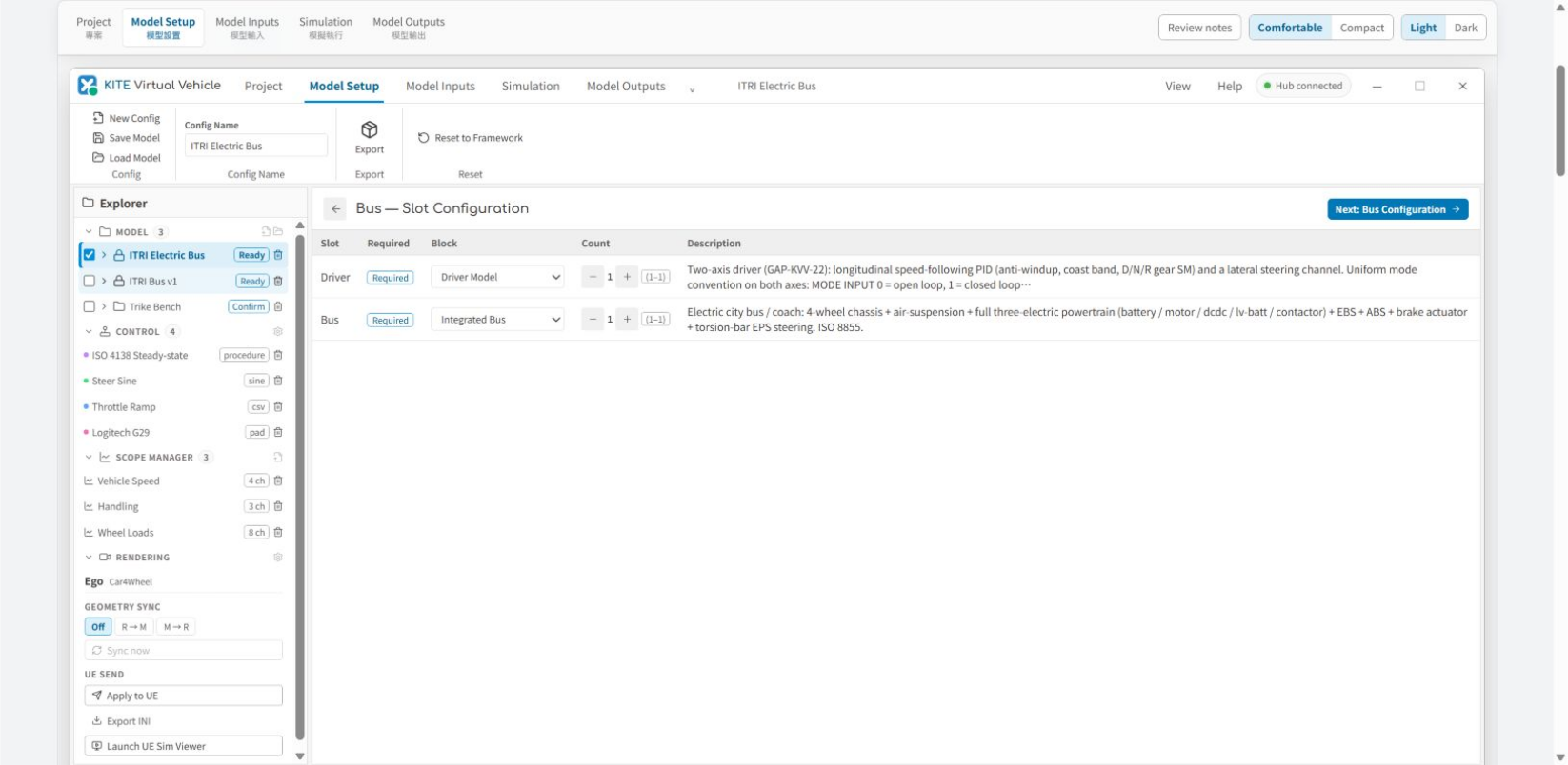
Screen 02 / 10
Confirm required slots such as the driver and vehicle model, select the block and instance count for each slot, then continue to vehicle configuration.
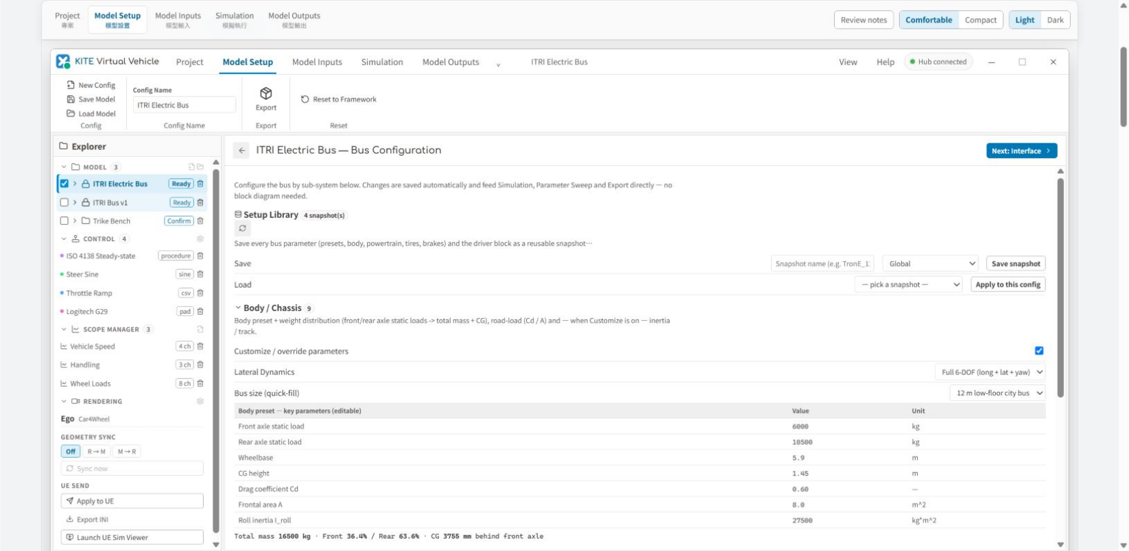
Screen 03 / 10
Open the matching bus, car, or plant setup for the selected framework; manage body and chassis, powertrain, braking, steering, tires, and reusable snapshots.
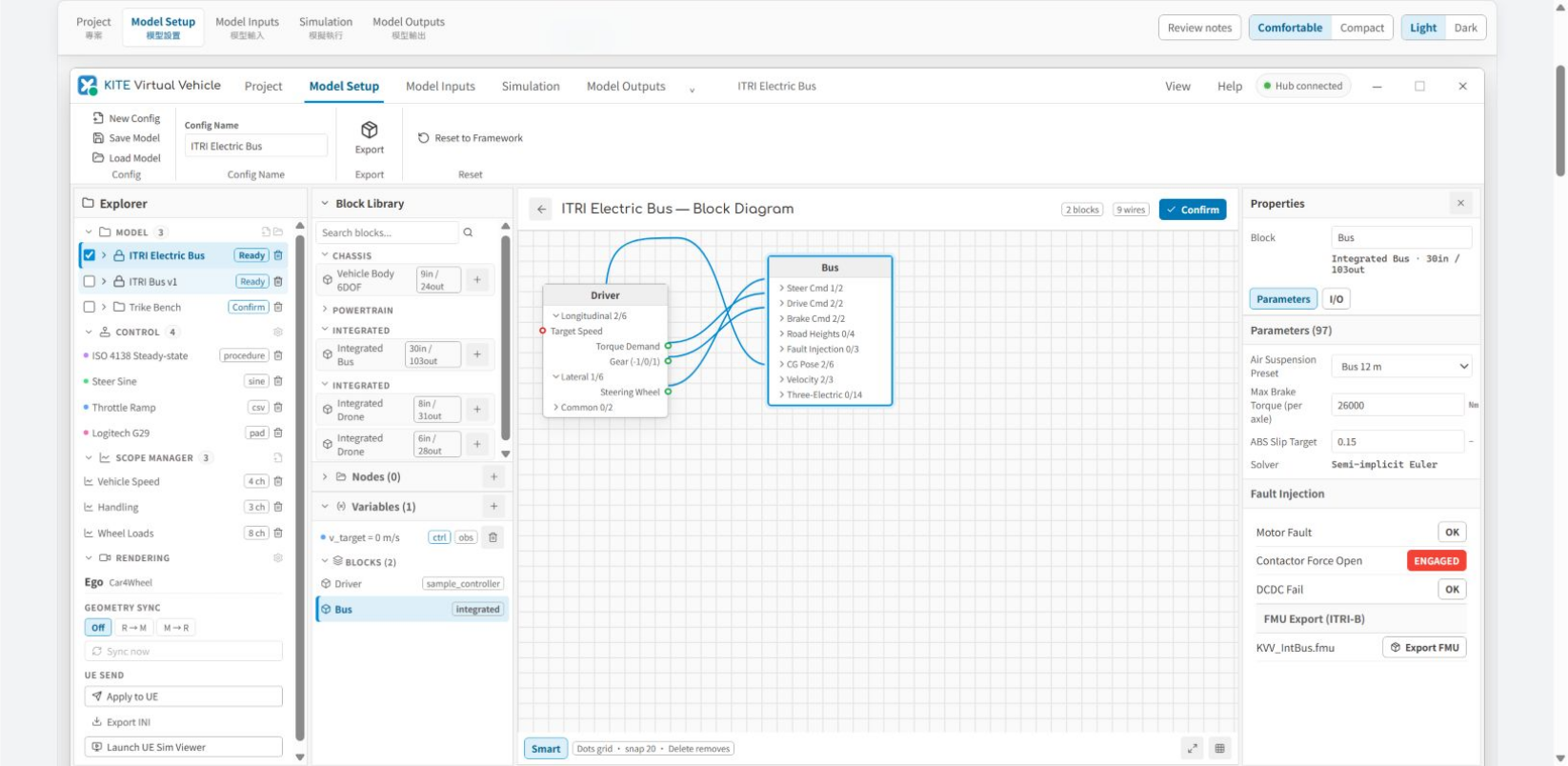
Screen 04 / 10
Inspect the driver, vehicle model, ports, and wiring in the block diagram, then adjust parameters, fault injection, and FMU export in Properties.
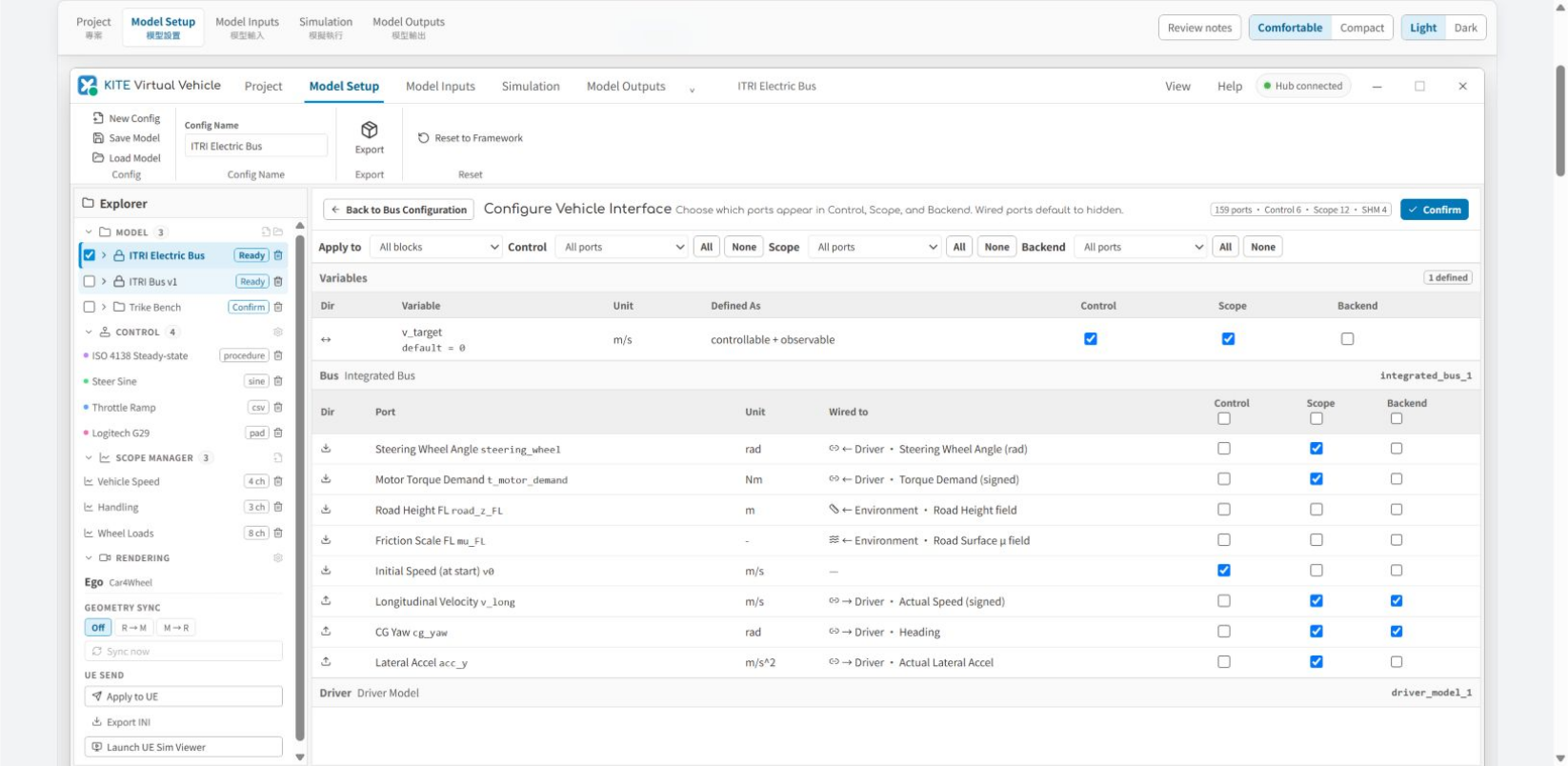
Screen 05 / 10
Choose which variables and ports are exposed to Control, Scope, Backend, and SHM, and verify their Wired to relationships.
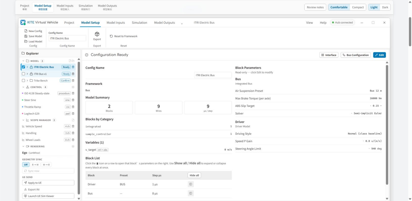
Screen 06 / 10
Review the framework, blocks, wires, step time, variables, and key parameters on Configuration Ready before moving into Simulation.
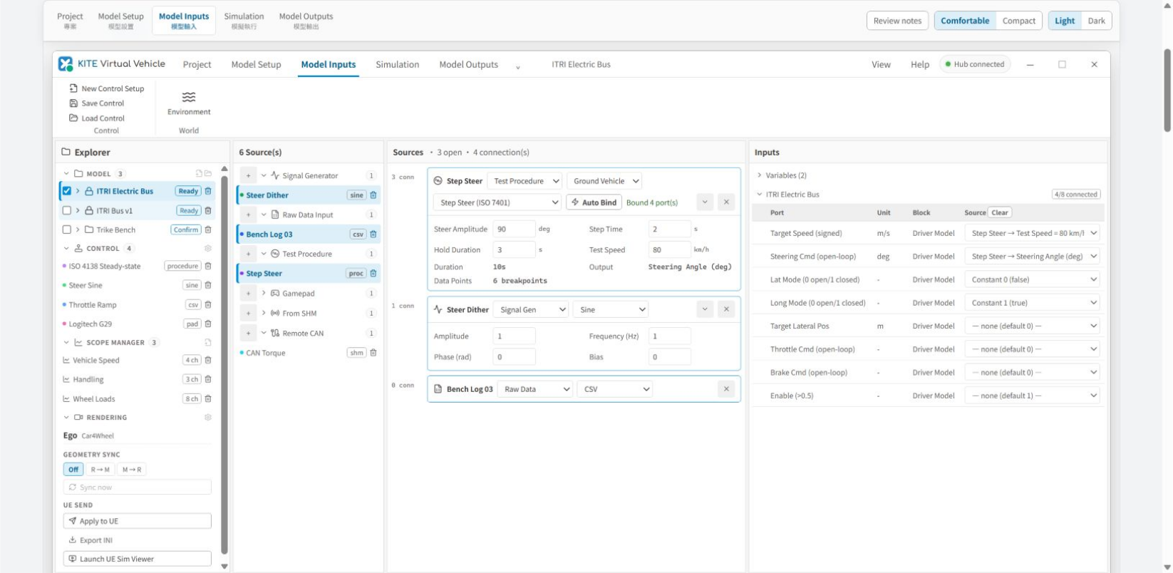
Screen 07 / 10
Combine test procedures, signal generators, raw data, gamepads, SHM, or Remote CAN and map them to model input ports with Auto Bind.
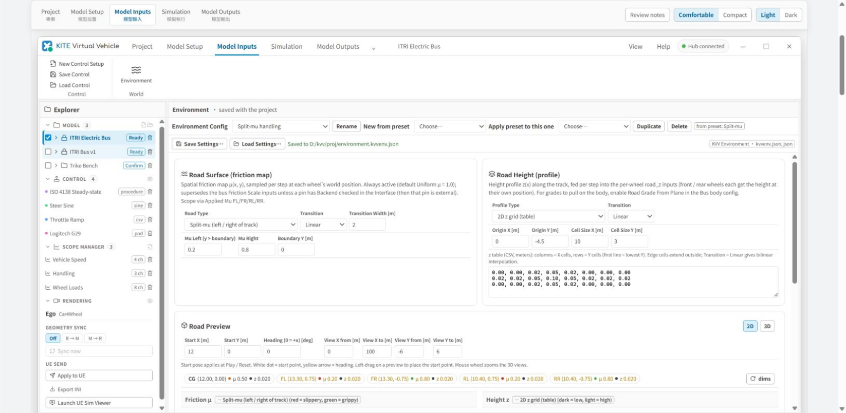
Screen 08 / 10
Configure the road-surface friction map, road-height profile, wind, and ambient air, then preserve the environment setup in the project.
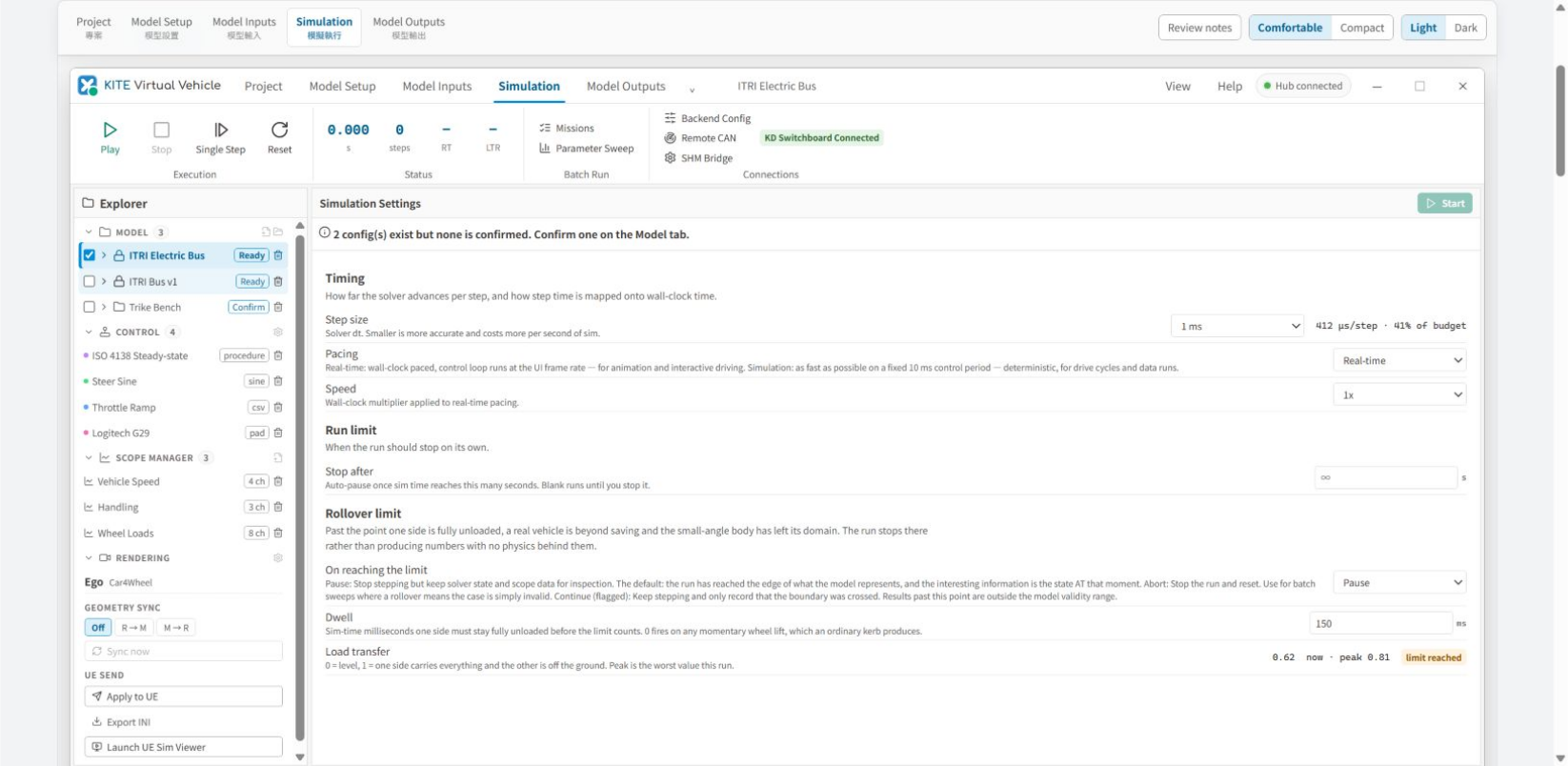
Screen 09 / 10
Set step size, real-time or simulation pacing, run and rollover limits, then use single-step execution, missions, parameter sweeps, and external connections.
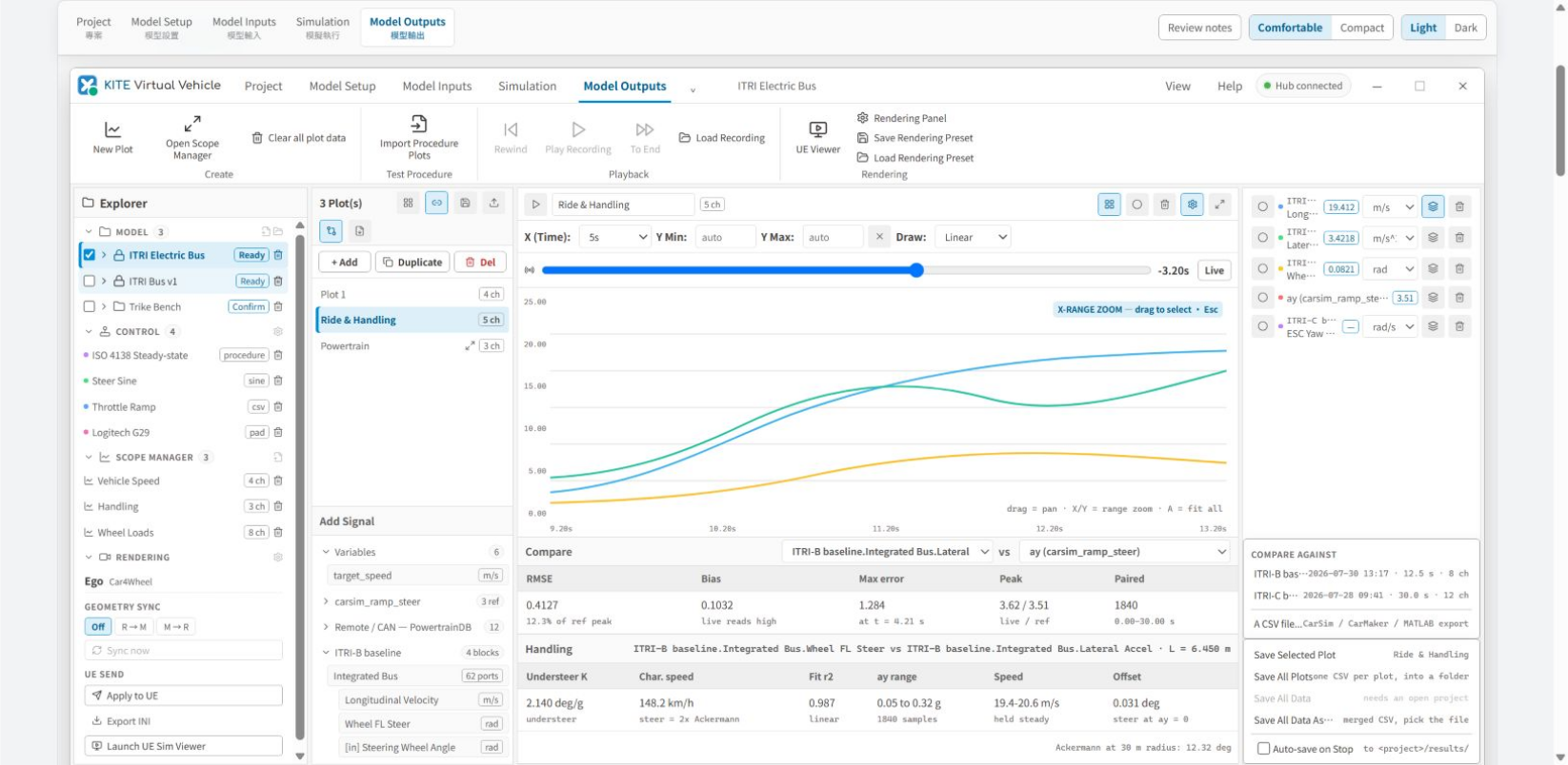
Screen 10 / 10
Review multichannel plots, comparison baselines, and result metrics in Scope, then manage recordings, playback, and CSV output.
Model Framework entry points cover cars, buses, trucks, two-wheelers, trikes, helicopters, drones, multirotor UAVs, and fixed-wing models.
Control sources include test procedures, signal generators, raw data, gamepads, Remote CAN, and SHM mapped to model input ports.
The result workflow provides scopes, recording, playback, missions, parameter sweeps, FMU export, KD Switchboard, and UE Viewer.
Start from a framework or .kvvmodel preset and manage .tir, DBC, FMU, drive-cycle, and vehicle-configuration assets.
Configure body, suspension, tires, steering, powertrain, braking, and Driver / Pilot interfaces, or compose model topology in a block diagram.
Assign Control, Scope, Backend, and SHM exposure to model ports while separating controllable and observable signals.
Configure test procedures, signal generators, raw data, gamepads, road surface, road height, wind, and ambient air.
Run with real-time or fixed control periods, then use single-step execution, missions, and parameter sweeps for repeatable comparisons.
Plot signals, save CSV, replay recordings, and connect KD Switchboard, Remote CAN, SHM Bridge, UE Viewer, or FMU co-simulation.
Start from vehicle assets and models, then define inputs, execution, and outputs so interactive driving, test procedures, batch missions, and parameter sweeps share one model.
01 / 05
Create or open a project and load .kvvmodel, .tir, DBC, FMU, raw-data, or drive-cycle assets.
02 / 05
Select a model framework and configure slots, vehicle subsystems, block diagrams, and port interfaces.
03 / 05
Map test procedures, signal generators, raw data, gamepads, Remote CAN, or SHM to the model and configure road and environment conditions.
04 / 05
Choose real-time or simulation pacing, set dt, run limits, and model boundaries, then play, stop, reset, or single-step.
05 / 05
Use scopes, recording, playback, missions, and parameter sweeps, then export CSV / FMU or connect KD Switchboard / UE Viewer.
Designed for teams that need a vehicle plant, controller inputs, repeatable procedures, batch comparisons, and replayable results before vehicle or HIL testing.
Drive vehicle models with a Driver Model, signal generator, test procedure, or gamepad before vehicle testing.
Create bus, truck, car, two-wheeler, trike, or aerial vehicle configurations and preserve parameters plus interface settings.
Use step steer, ramp steer, sine with dwell, acceleration, braking, or drive-cycle procedures as repeatable inputs.
Run parameter-sweep variants and compare speed, acceleration, steering, energy, and model-boundary metrics.
Connect controllers, data backbones, and visualization environments through FMU, KD Switchboard, Remote CAN, SHM Bridge, and UE Viewer.